I have been rewriting this part completely new in C++. So at the moment a lot of the following is out of date.
- Culvert at dike
To discharge water from island to sea - Pumping station with pipes
To discharge water from island to sea - Ditches
- Discharge water to Pumping-station of culvert at dike
- Weirs
To control waterlevel ditch - Culvert in ditch
When ditch has to cross road - Lakes / surface water
For storage of surplus of rainfall - Sewer pipe
- Storage settling basin (BBB)
The dynamic water system on land is programmed as a blueprint.
FD_Surfacewater contains both the logic and the assets of the water system. The backbone of the FD_Surfacewater is a spline with points. The points represent a change in the water system, for example: input discharge, different structure (pipe, channel, weir..), different dimension. So each point (=Node) is connected with the database WaterSystemData. So in between 2 points (=branch) of the backbone spline, everything is the same, based on the information of the downstream point.. Spline and point represent the bedlevel of the structure.
Index 0 spline is downstream
Al the programming is done in the so called construction script. This is a cool feature of Unreal Engine. Al programmed calculations can be done in the editor. It is for example not necessary to run the game, to see what waterlevels will occur. They are already calculated in the editor.
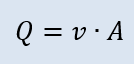
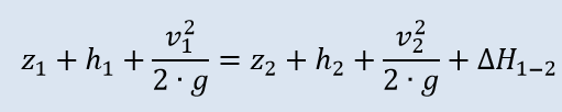
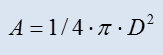
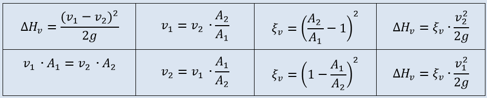
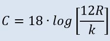
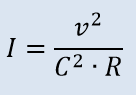
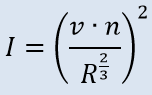
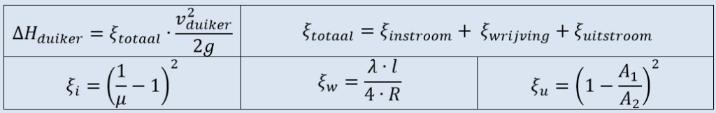
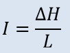
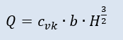
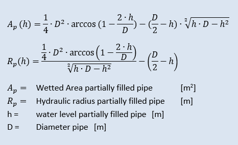
Formulas used for calculation water levels

Some general Notes:
- The basis of the watersystem is a spline. Between 2 nodes the structure is the same. The location of the spline is the bedlevel.
- A FD_Surfacewater is one line with no branches and has a fixed direction of flow.
- A dendritic system is possible, because the 3D world may contain different FD_Surfacewater which are connected at points. When calculation a dendritic system the sequence of making calculations is important.
- Strategy for calculating the water-system.We assume a stationary flow. So new calculations are only made when changes are made to the water-system. In the future calculations will be made per time-step and change in storage will also be taken into account.
Link to page with formulas used - To get access to the information, or to change information menu are used.
Link to page Navigation - Internal Unreal uses centimeters, the
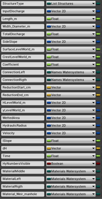
FD_Surfacewater uses m - Backbone of FD_Surfacewater is the WaterDataStruct which stores all data (also calculated data) for each branch.
Connect side branches
- Information on side branch is stored in [ConnectionLeft] and/or [ConnectionRight]
- In FD_GameMode: FD_WaterSystemsref and FD_WatersystemName. Note This does not work in constructionscript ? So it should be a separate function in the constructionscript.
- New function Find_Side_Branches
- Changed variable InputDischarge to a 2dvector. x = de input branch, y is the input from sidebranches
Design Manhole / Sewer
- If 2 pipes don’t have the same bedlevels, the difference in height is stored in With_Diameter_m.y. Adding this height is only applied the x downstreampoint
- Manhole is not a separate branch, but is generated when 2 culvert pipes branches connect.
- The check on manhole is made when type is culvert. If type_down also is a culvert, a manhole can be added.
- Switch to add manhole is :
When diameter pipes is different, manhole is added automatically
When diameter pipes are the same, the following switch is used.
Slope X = 1 add manhole, Slope X = 0 no manhole - A Boolean variable Manhole is defined.
- Manhole is always a rectangle, with max 4 pipes connected. So 2 other BP_watersytems could be connected to the manhole.
- Alle dimensions in m
- When function manhole is activated the following information is defined:
– bedlevel, based on 4 connections
– D1, D2 (left), D3, D4(right)
– Width manhole based on D1 and D4. Width = Max D1 / D3 + 0,6 m
– Length manhole based on D2 en D4. Length = Max D2 / D4 + 0,6 m
– Length manhole / 2 = reduction length (m)
– Surfacelevel is de highest surfacelevelworld of the 4 connections - Manhole is activated before the pipe is drawn. This because the reduction length.
- Information from the array is also necessary for the Reduction Length for ending and starting pipe.
Design weir
- Exists of 3 parts, left – middle (=crest) – left
- Width_Diameter_m.x = width weir.
- Width_Diameter_m.y = width sides
Blueprints used:
- Blueprint reference
- Documention in splines
- Math Node
- SaveGame
- Structs
- Array nodes
- Set Members in Struct node
- Flow control
- Select Node
- All spline Nodes
- Format Text
- Sequence node
- Flow control
- Division (whole and remainder)